
 Italian
 German
 Russian
 Turkish
 Portuguese
 Spanish
 French

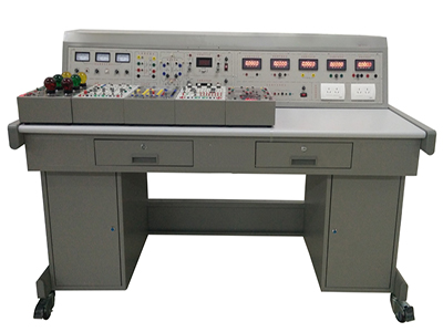
GLCG-DG-2A open type electrical and electronic training equipment is a new generation of advanced experimental equipment launched by our company. This experimental equipment fully considers the current situation and development trend of practical teaching, combines virtual and real, verification, comprehensive, innovative and open and autonomous experiments, and aims to improve students' hands-on ability and innovation ability. The product is well designed and has stable and reliable performance. All circuits and experimental modules are fully modularized, which is more suitable for users to flexibly configure and select according to the characteristics of their own schools and courses.
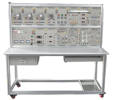
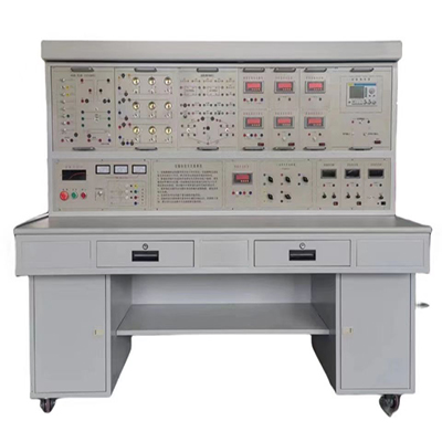
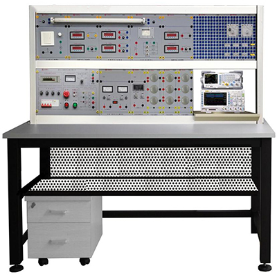
GLCG-DG-2A electrical and electronic training equipment
Ⅰ、 Overview
GLCG-DG-2A open type electrical and electronic training equipment is a new generation of advanced experimental equipment launched by our company. This training equipment fully considers the current situation and development trend of practical teaching, and combines virtual and real, verification, comprehensive, innovative and open and autonomous experiments to improve students' hands-on ability and innovation ability. The product is well designed, stable and reliable in performance, and is more suitable for customers to flexibly configure and select according to the characteristics of their own schools and courses.
Ⅱ、Technical and performance indicators
This equipment includes the following components: power module, test instrument module, multifunctional tester for electrical and electronic components, circuit basic experiment module, AC circuit, magnetic circuit and transformer experiment module, low-voltage electrical experiment module, analog circuit experiment module and digital circuit experiment module, and is equipped with matching experimental connection wires.
1. Power supply: standard three-phase five-wire AC380V±10%, 50Hz; device capacity: ≤1.5kVA
2. Power module
Provides three-phase 0~450V adjustable AC power, and can also obtain single-phase 0~250V adjustable power (equipped with a three-phase axial linkage auto-coupling voltage regulator). The adjustable AC power output is equipped with overcurrent protection technology, which can automatically protect against phase-to-phase, line-to-line overcurrent and direct short circuit. The three-phase power supply passes through the key switch and contactor to the isolation transformer, and then through the three-phase voltage regulator output, so that the output is isolated from the power grid, which plays a certain protective role for personal safety; voltage-type leakage protection device and current-type leakage protection device are required for leakage protection.
3. Test instrument module
(1) Five-digit intelligent single-phase multi-function meter
AC current: 0.0000~5.0000A; AC voltage: 0.0000~500.00V, measurement accuracy is 0.5 level, full range automatic switching gear. The meter initially displays active power. By pressing the buttons on the panel, it can display parameters such as AC voltage, AC current, single-phase active power, single-phase reactive power, power factor, frequency, load properties (R\L\C), etc.
(2) Five-digit intelligent AC digital voltmeter
Five-digit high-visibility LED digital display, measurement range: 0.0000~500.00V, with automatic gear switching, arbitrary range setting and manual gear shifting function. The range can be set arbitrarily within the range of 0~500.00V to ensure measurement accuracy, with over-range alarm, LED indication and protection. The manual range is initially set to 2V, 20V, 200V, 500V. The measurement accuracy is 0.5 level. It is designed with dedicated DSP digital measurement chip and microprocessor technology, and has power-off protection and watchdog circuit.
(3) Five-digit intelligent AC digital ammeter
Five-digit high-visibility LED digital display, measuring range: 0.0000~5.0000A, with automatic gear switching, arbitrary range setting and manual gear shifting function. The range can be set arbitrarily within the range of 0~5.0000A to ensure measurement accuracy, with over-range alarm, LED indication and protection. The manual range is initially set to 200mA, 2A, 5A. The measurement accuracy is 0.5 level. It is designed with dedicated DSP digital measurement chip and microprocessor technology, with power-off protection and watchdog circuit.
(4) Five-digit intelligent DC voltmeter
Five-digit high-visibility LED digital display. Measuring range: 0.0000~500.00V, with automatic gear switching, arbitrary range setting and manual gear shifting function. The range can be set arbitrarily within the range of 0~500.00V to ensure measurement accuracy, with over-range alarm, LED indication and protection. The manual range is initially set to 2V, 20V, 200V, and 500V. The measurement accuracy is 0.5. It is designed with a dedicated DSP digital measurement chip and microprocessor technology, and has power-off protection and a watchdog circuit.
(5) Five-digit intelligent DC ammeter
Five-digit high-visibility LED digital display. Measuring range: 0.0000~2000.0mA, with automatic gear switching, arbitrary range setting, and manual gear shifting function. The range can be set arbitrarily within the range of 0~2000.00mA to ensure measurement accuracy, with over-range alarm, LED indication and protection. The manual range is initially set to 20mA, 200mA, and 2000mA. The measurement accuracy is 0.5. It is designed with a dedicated DSP digital measurement chip and microprocessor technology, and has power-off protection and a watchdog circuit.
4. DC constant voltage and constant current power supply module
Uses pointer type or three-and-a-half-digit digital instrument to display output voltage and current value, can output two groups of independent 0-30V/1A adjustable constant voltage source and one group of independent 0-200mA adjustable constant current source, all with overload, short circuit protection and self-recovery functions. The adjustable constant voltage source is continuously adjustable without grade, and the output has long-term short circuit protection and self-recovery function. The adjustable constant current source is divided into three grades of 2mA, 20mA, and 200mA, with a maximum output power of 15W, starting from 0mA, with an adjustment accuracy of 1%, load stability ≤5×10⁻⁴, rated change rate ≤5×10⁻⁴, with output open circuit and short circuit protection functions.
5. Circuit basic experiment module
All basic circuit experiment modules adopt building block design. The building blocks are equipped with resistors, potentiometers, capacitors, inductors, integrated circuits, connectors, test sockets, short-circuit bridges and other devices and circuit connection and test component modules, which can carry out the following circuit basic experiments:
1) Measurement and error analysis of commonly used electrical instruments;
2) Error reduction methods and range expansion of instruments;
3) Mapping of circuit element volt-ampere characteristics and measurement of power supply external characteristics;
4) Research on voltage source, current source and their power supply equivalent transformation;
5) Kirchhoff's law and superposition principle experiment;
6) Thevenin theorem and Norton theorem experiment;
7) Study of controlled source characteristics;
8) Determination of impedance characteristics of R, L, C components;
9) Response test of first-order and second-order circuits;
10) Study of R, L, C series resonant circuit;
11) Study of passive two-port network.
6. AC circuit, magnetic circuit and transformer experimental module
Equipped with resistors, capacitors, inductors, bulbs, fluorescent lamps, switches, ballasts, starters, magnetic circuit mutual inductors, transformers, connectors, test sockets, short-circuit bridges and other devices and circuit connection and testing components, the following AC circuit experiments can be carried out:
1) Research on phasors of sinusoidal steady-state AC circuits;
2) Measurement of voltage and current of three-phase AC circuits;
3) Measurement of power of three-phase circuits;
4) Phase sequence measurement of three-phase circuits;
5) Application of transformers;
6) Research on mutual inductance circuits, etc.
7. Low-voltage electrical experimental module
Equipped with AC contactors, thermal relays, buttons, connectors, test sockets, short-circuit bridges, three-phase thyristor main circuits, three-phase thyristor trigger circuits, motor speed control experimental modules and other components or assemblies, the following low-voltage electrical and power electronics experiments can be carried out:
1) Inching and self-locking control of three-phase squirrel cage asynchronous motors;
2) Forward and reverse control of three-phase squirrel cage asynchronous motors.
8. Provide DDS arbitrary waveform generator
(1) Frequency and amplitude digital potentiometers are continuously adjustable, without frequency band selection key and attenuation key.
(2) 3.2-inch high-brightness TFT color liquid crystal display, simultaneously displaying dual-channel output waveforms. Output frequency: 0. 0000~10MHz, minimum frequency resolution can reach 10u Hz: output amplitude 0~20VP-P, minimum amplitude resolution can reach 10mV.
(3) Signal type: sine wave, triangle wave, square wave, rectangular wave, sawtooth wave, arbitrary wave, etc.:
(4) Adjustable parameters: duty cycle adjustment, attenuation adjustment, -100%~+100% DC bias adjustment, phase difference adjustment, frequency adjustment, amplitude adjustment, etc.:
(5) With frequency measurement, period measurement, positive and negative pulse width measurement, duty cycle measurement and counting functions:
(6) With communication function, fully open communication protocol, can be controlled by PC, and can edit arbitrary waveforms on PC and download them to the instrument output waveform.
9. Analog circuit experiment module
Equipped with electronic devices, experimental expansion modules, connectors, test sockets, short-circuit bridges, matching analog circuit integrated circuits and other components, it can carry out the following electronic circuit experiments:
1) Transistor common emitter single tube amplifier;
2) Field effect tube amplifier;
3) Negative feedback amplifier;
4) Emitter follower;
5) Differential amplifier;
6) Integrated operational amplifier index test;
7) Basic application of integrated operational amplifier (I) - analog operational circuit;
8) Basic application of integrated operational amplifier (II) - signal processing (active filter);
9) Basic application of integrated operational amplifier (III) - signal Processing (voltage comparator);
10) Basic application of integrated operational amplifier (IV) - signal processing (waveform generator);
11) RC sine wave oscillator;
12) LC sine wave oscillator;
13) Assembly and debugging of function signal generator;
14) Voltage controlled oscillator;
15) Low frequency power amplifier (I) - OTL power amplifier;
16) Low frequency power amplifier (II) - integrated power amplifier;
17) DC regulated power supply (I) - series transistor regulated power supply;
18) DC regulated power supply (II) - integrated voltage regulator;
19) Thyristor controlled rectifier circuit;
20) Application experiment - temperature monitoring and control circuit.
10. Digital circuit experiment module
Equipped with electronic devices, experimental expansion modules, connectors, test sockets, short-circuit bridges, supporting digital circuit integrated circuits and other components, it can carry out the following electronic circuit experiments:
1) Transistor switching characteristics, limiters and clamps;
2) TTL integrated logic gate logic function and parameter test;
3) CMOS integrated logic gate logic function and parameter test;
4) TS gate, OC gate function test and application;
5) Determination of performance and parameters of different series of TTL chips;
6) Gate circuit driving capability test;
7) Logic pen experiment and analysis;
8) TTL and CMOS interconnection experiment;
9) Combinational logic circuit and its application;
10) Combinational logic circuit analysis and design;
11) Competition adventure;
12) Trigger
13) Trigger application;
14) Register and its Application;
15) Timing circuit test and application;
16) Sequential pulse and pulse distributor circuit;
17) Integrated counter;
18) Decoder and data selector;
19) Counting decoding display circuit;
20) 555 integrated timer and its application;
21) Waveform generator and monostable trigger;
22) Schmitt trigger and its application;
23) Multi-channel analog switch and its application;
11. Experimental table specifications: 1600mm*800mm*1460mm
12. Experimental connection wire
GLCG-DG-2A open type electrical and electronic training equipment adopts high-reliability sheath structure plug connection wire (no possibility of electric shock), oxygen-free copper wire is used to draw hair-thin multi-strand wire, covered with nitrile polyvinyl chloride insulation layer, and the plug adopts solid copper parts with beryllium light copper shrapnel, which is safe and reliable in contact.
III、Experimental Projects
(I) Basic Electrical Experiments
1. Use of basic electrical instruments and calculation of measurement errors
2. Methods to reduce instrument measurement errors
3. Measurement and mapping of volt-ampere characteristics of linear and nonlinear circuit elements
4. Determination of potential and voltage and drawing of circuit potential diagrams
5. Verification of Kirchhoff's laws and fault diagnosis
6. Verification of superposition theorem and fault diagnosis
7. Equivalent transformation of voltage source and current source
8. Verification of Thevenin's theorem
9. Verification of Norton's theorem
10. Two-port network test
11. Verification of reciprocity theorem
12. Experimental study of controlled sources VCCS, VCVS, CCVS, CCCS
13. Observation and measurement of typical electrical signals
14. Test of RC first-order circuit response
15. Study of second-order dynamic circuit response
16. Test of impedance characteristics of R, L, C elements
17. Test of RC series and parallel frequency selection network characteristics
18. R, L, C Research on series resonant circuits
19. Using the three-meter method to measure equivalent parameters of AC circuits
20. Research on phase quantities of sinusoidal steady-state AC circuits (experiment to improve power factor of fluorescent lamps)
21. Mutual inductance experiment
22. Testing of single-phase iron core transformer characteristics
23. Measurement of voltage and current of three-phase AC circuits
24. Measurement of power of three-phase circuits
25. Calibration of single-phase watt-hour meters
26. Measurement of power factor and phase sequence
(Ⅱ) Analog circuit experiment
1. Use of common electronic instruments (see the experimental appendix for the principle and use of oscilloscope)
2. Transistor common emitter single tube amplifier
3. Field effect tube amplifier
4. Negative feedback amplifier
5. Emitter follower
6. Differential amplifier
7. Integrated operational amplifier index test
8. Basic application of integrated operational amplifier I—analog operational circuit
9. Basic application of integrated operational amplifier II—signal processing (active filter)
10. Basic application of integrated operational amplifier III—signal processing (voltage comparator)
11. Basic application of integrated operational amplifier IV—signal processing (waveform generator)
12. RC sine wave oscillator
13. Voltage controlled oscillator
14. Low frequency power amplifier I—OTL power amplifier
15. Low frequency power amplifier II—integrated power amplifier
16. DC regulated power supply II—integrated voltage regulator
17. Thyristor controlled rectifier circuit
(Ⅲ) Digital circuit experiment
1. Transistor switching characteristics, limiter and Clamp
2. Logical function and parameter test of TTL integrated logic gate
3. Logical function and parameter test of CMOS integrated logic gate
4. Connection and drive of integrated logic circuit
5. Design and test of combinational logic circuit
6. Decoder and its application
7. Data selector and its application
8. Trigger and its application
9. Counter and its application
10. Shift register and its application
11. Pulse distributor and its application
12. Use gate circuit to generate pulse signal - self-excited multivibrator
13. Monostable trigger and Schmitt trigger - pulse delay and waveform shaping circuit
14. 555 time base circuit and its application
15. D/A, A/D converter
(IV) Electric traction experiment
1. Three-phase asynchronous motor inching and self-locking control circuit
2. Three-phase asynchronous motor forward and reverse control circuit
3. Three-phase asynchronous motor Y-Δ step-down starting control circuit
4. Three-phase asynchronous motor energy consumption braking control
5. Three-phase asynchronous motor starting sequence control

Synchronous PC version:
GLCG-DG-2A electrical and electronic training equipment https://www.biisun.com/home/category/detail/id/143.html