
 Italian
 German
 Russian
 Turkish
 Portuguese
 Spanish
 French
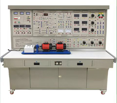

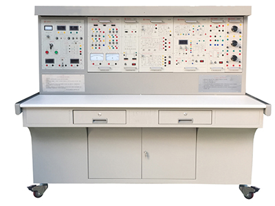
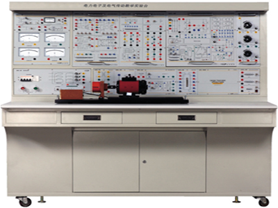
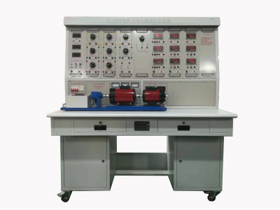
GL-DLDZ-1A power electronics technology and motor control experimental equipment is carefully developed based on the requirements of the latest unified textbooks of colleges and universities, such as "Power Electronics Technology" (4th edition) and "Electric Traction Automatic Control System" (3rd edition), absorbing the advantages of similar products at home and abroad, and taking full account of the current situation and development trend of the laboratory. Among similar products, it has the advantages of reasonable structure, complete functions, good reliability, and high cost performance.
GL-DLDZ-1A power electronics technology and motor control experimental equipment
Ⅰ. Product Overview
GL-DLDZ-1A power electronics technology and motor control experimental equipment is based on the requirements of the latest unified textbooks of colleges and universities, such as "Power Electronics Technology" (4th edition) and "Electric Traction Automatic Control System" (3rd edition). It absorbs the advantages of similar products at home and abroad, fully considers the current situation and development trend of the laboratory, and is carefully developed. Among similar products, it has the advantages of reasonable structure, complete functions, good reliability, and high cost performance.
Ⅱ. Product Features
1. Strong comprehensiveness This device integrates the current experimental projects of power electronics, semiconductor conversion, AC and DC speed regulation, AC frequency conversion, motor control, control theory, etc. in various schools in China.
2. Strong adaptability It can meet the experimental teaching of corresponding courses in various schools. The depth and breadth can be flexibly adjusted according to needs. Popularization and improvement can be organically combined according to the progress of teaching. The device adopts a building block structure, which is easy to replace. If you need to expand functions or develop new experiments, you only need to add components, and it will never be eliminated.
3. Strong completeness From special power supply, motor and other experimental components to special wires for experimental connection, the performance and specifications of the supporting components are closely matched with the needs of the experiment.
4. Strong intuitiveness Each experimental pendant adopts a separated structure, the component panel is schematic, the lines are clear, the tasks of each pendant are clear, and the operation and maintenance are convenient.
5. Strong scientificity The device occupies a small area, saves experimental space, and reduces infrastructure investment; the supporting small motors are specially designed to simulate the characteristics and parameters of small and medium-sized motors; small motors consume less power, save energy, and have low experimental noise, neat and beautiful, improving the experimental environment; the experimental content is rich and the design is reasonable. In addition to deepening theoretical knowledge, design experiments can also be combined with actual practice.
6. Strong openness The control panel power supply is isolated by a three-phase isolation transformer, and is equipped with a voltage-type leakage protection device and a current-type leakage protection device to ensure the safety of the operator; each power output has monitoring and short-circuit protection functions, and each measuring instrument has a reliable protection function, which is safe and reliable to use; the control panel is also equipped with an experimental manager to provide a unified standard for the assessment of students' experimental skills. Since the whole set of equipment has been carefully designed, with reliable components and reliable processes as guarantee, the product performance is excellent, which creates conditions for open laboratories.
7. Strong advancement The equipment focuses on the new device height. On the basis of retaining the thyristor experiment, it adds a large number of modern power electronics technology experiments on the characteristics of new devices, the driving of new devices and typical new device applications, so that students can have sufficient knowledge and understanding of new devices and keep up with the pace of the times.
III. Equipment configuration
1. DL01 power control panel
(1) AC power supply (all with overcurrent protection measures)
Provide AC power supply: DC speed control gear is three-phase AC 200V/3A
AC speed control gear is three-phase AC 240V/3A
(2) High-voltage DC power supply
Excitation power supply: 220V (0.5A), with output short-circuit protection.
(3) Digital instruments
1) AC digital voltmeter: can indicate the input line voltage of the three-phase power grid through the band switch below it, with an accuracy of 1.0 level;
2) One true effective value AC digital voltmeter: measurement range 0~500V, automatic range judgment and automatic switching, accuracy 0.5 level, three-and-a-half-digit digital display, providing voltage indication for the AC speed regulation system;
3) One true effective value AC digital ammeter: measurement range 0~5A, automatic range judgment and automatic switching, accuracy 0.5 level, three-and-a-half-digit digital display, with over-range alarm, indication and total power cut-off functions, providing current indication for the speed regulation system;
4) One DC digital voltmeter: measurement range 0~300V, three-and-a-half-digit digital display, input impedance of 10MΩ, accuracy 0.5 level, providing voltage indication for the reversible speed regulation system;
5) One DC digital ammeter: measurement range 0~5A, three-and-a-half-digit digital display, accuracy 0.5 level, with over-range alarm, indication, total power cut-off functions, providing current indication for the reversible speed regulation system.
(4) Personal safety protection system
A set of three-phase isolation transformers: The three-phase power supply first passes through the three-phase leakage protector, and then through the key switch and contactor to the isolation transformer, so that the output is isolated from the power grid (floating ground design), which plays a certain protective role in personal safety.
Voltage type leakage protector 1: Protects against leakage in the line before the isolation transformer, trips the contactor in the control panel, and cuts off the power supply.
Voltage type leakage protector 2: Protects against leakage in the line after the isolation transformer and the wiring during the experiment, sends out an alarm signal and cuts off the power supply to ensure personal safety.
Current type leakage protection device: If there is leakage in the control panel, the leakage current exceeds a certain value, and the power supply is cut off.
Experimental connection wires and sockets: Strong and weak current connection wires and sockets are separated and cannot be mixed. Strong current connection wires and sockets adopt a fully enclosed process, which is safe, reliable and prevents electric shock.
(5) Other facilities of the control panel
In the large groove on the front of the control panel, there are two stainless steel pipes for hanging experimental components. The bottom of the groove is equipped with 12-core, 10-core, 4-core, and 3-core sockets. The power supply of the hanging box is provided by these sockets. Single-phase three-pole 220V power sockets and three-phase four-pole 380V power sockets are set on both sides of the control panel. There is also a 40W fluorescent lamp for lighting the experimental device.
2. DL02 experimental table
The experimental table is an iron double-layer matte dense spray structure. The desktop is a fireproof, waterproof, wear-resistant high-density board with a solid structure and a rectangular closed structure. It is beautiful and generous in shape. It is equipped with two large drawers and cabinet doors for placing tools, pendants and materials. The desktop is used to install the power control panel and provides a spacious and comfortable work surface. The experimental table is also equipped with four universal wheels and four fixed adjustment mechanisms, which are easy to move and fix, which is conducive to the layout of the laboratory.
3. DJQ03-1 stainless steel motor rail, optical encoder speed measurement system (Japan Omron 1024 photoelectric encoder) and digital tachometer
4. DJQ27 three-phase adjustable resistor (900Ω×2/0.41A per group)
5. DL03 thyristor main circuit
12 5A/1000V thyristors are provided, divided into two groups of positive and negative bridges. Each thyristor is equipped with a protection device. The positive and negative bridge thyristors can be triggered by external signals (with a trigger pulse input interface), which can better complete the design experiment; there are precision pointer DC voltmeter with mirror ±500V, precision 1.0 level, DC ammeter with mirror ±5A, precision 1.0 level, one each and one smoothing reactor.
6. DL04 three-phase thyristor trigger circuit
Three-phase trigger circuit, power amplifier circuit, etc. are provided, which are used in conjunction with "DL03".
7. DL05 thyristor trigger circuit experiment
Provides five trigger circuits, including single junction transistor trigger circuit, sinusoidal synchronous phase shift trigger circuit, sawtooth synchronous phase shift trigger circuit, single-phase AC voltage regulation trigger circuit and Siemens TCA785 trigger circuit.
8. DL06 Motor speed control experiment (I)
Provides the following modules: current feedback and overcurrent protection (FBC+FA), setter (G), speed converter (FBS), reverser (AR), voltage isolator (TVD), regulator I and regulator II. The feedback resistors and capacitors of regulators I and II are external (obtained from DJK08). During the experiment, the system parameters can be flexibly changed to observe the effects of different parameters on system stability and response time. It also allows students to design the parameters of the regulator's amplification and integration time based on various parameters of the speed control system (such as the electromechanical time constant of the motor), and verify the actual results at the same time, so as to complete the design experiment.
9. DL07 DC chopper experiment
Designed based on the relevant DC chopper content in "Power Electronics Technology" (4th edition) edited by Professor Wang Zhaoan and Professor Huang Jun of Xi'an Jiaotong University; provides the components required to form a DC chopper circuit and uses a dedicated PWM control integrated circuit SG3525. It can complete six typical experiments in the textbook: Buck Chopper, Boost Chopper, Boost-Buck Chopper, Cuk Chopper, Sepic Chopper, and Zeta Chopper.
10. DL08 Given and experimental devices
Provide given (±15V adjustable voltage output), varistor (as an overvoltage protection element, internally connected in a triangle connection), diode, 24V power supply and inductor.
11. DL09 New device characteristic experiment
Provides SCR, MOSFET, IGBT, GTO, GTR new devices, used in conjunction with DL06, can measure their characteristic curves; used in conjunction with DL13, can complete the driving characteristic experiment of new power electronic devices.
12. DL10 adjustable resistor and capacitor box
Provides three sets of adjustable capacitors with a withstand voltage of AC63V, with an adjustment range of 0.1~11.37uF, and two sets of decimal adjustable resistors with a range of 0~999KΩ.
13. DL11 single-phase voltage regulation and adjustable load
Provides a 0~250V/0.5KVA single-phase AC auto-coupling voltage regulator to provide an adjustable power supply for the corresponding experiments; a rectifier filter circuit and a 0~90Ω/1.3A (series) or 0~45Ω/2.6A (parallel) ceramic disc adjustable resistor to provide an adjustable resistive load for the corresponding experiments.
14. DL12 transformer experiment
Provide a three-phase core transformer (the transformer has two sets of secondary windings, the primary and secondary winding voltages are 127V/63.6V/31.8V), which is used for asynchronous motor series speed regulation experiments and three-phase bridge and single-phase bridge active inverter circuit experiments; it also has a three-phase uncontrolled rectifier circuit and an inverter transformer.
15. DL17 dual closed-loop H-bridge DC/DC conversion DC speed regulation system
The purpose of speed regulation of reversible DC separately excited motor is achieved by triggering and controlling the IGBT tubes on the four bridge arms. It mainly consists of three parts, namely the main circuit part, the control circuit part and the regulation part. The main circuit consists of a DC power supply and four IGBT tubes; the control circuit part generates PWM pulse waves by a dedicated chip, and the four control pulses generated by the PWM wave pulse generator drive the IGBT tubes of the four bridge arms respectively; the regulation part consists of two PI regulators, and the feedback loop composed of the speed loop and the current loop makes the motor run stably at a given speed. The experimental projects that can be completed are: (1) Full-bridge DC/DC conversion circuit experiment (2) Double closed-loop reversible DC pulse width modulation experiment.
16. DJQ07-1 DC generator
17. DJQ09 DC shunt motor
18. DJQ11 three-phase wire-wound asynchronous motor
19. DL30 wire-wound asynchronous motor rotor special box
20. Experimental connection wires are equipped with two different experimental connection wires. The strong current part adopts a high-reliability sheath structure pistol plug connection wire (there is no possibility of any electric shock). The oxygen-free copper wire is drawn into a hair-thin multi-strand wire, which is covered with a nitrile polyvinyl chloride insulation layer, and the contact is safe and reliable; the weak current part adopts an elastic beryllium light copper bare structure connection wire. The two wires are matched with sockets with corresponding inner holes, which greatly improves the safety and rationality of the experiment.
IV. Experimental projects of power electronics technology and motor control experimental equipment
(I) Experimental projects of power electronics technology
1. Single junction transistor trigger circuit
2. Sine wave synchronous phase shift trigger circuit experiment
3. Sawtooth wave synchronous phase shift trigger circuit experiment
4. Single-phase half-wave controlled rectifier circuit experiment
5. Single-phase bridge half-controlled rectifier circuit experiment
6. Single-phase bridge full-controlled rectifier and active inverter circuit experiment
7. Three-phase half-wave controlled rectifier circuit experiment
8. Three-phase bridge half-controlled rectifier circuit experiment
9. Three-phase half-wave active Inverter circuit experiment
10. Three-phase bridge full-controlled rectifier and active inverter circuit experiment
11. Single-phase AC voltage regulation circuit experiment
12. Single-phase AC power regulation circuit experiment
13. Three-phase AC voltage regulation circuit experiment
14. Single-way thyristor (SCR) characteristic experiment
15. Gate turn-off thyristor (GTO) characteristic experiment
16. Power field effect tube (MOSFET) characteristic experiment
17. Power transistor (GTR) characteristic experiment
18. Insulated bipolar transistor (IGBT) characteristic experiment
(II) Experiments on typical power electronic device circuits
1. Full-bridge DC/DC conversion circuit experiment
2. Study on the performance of DC chopper circuits (step-down chopper circuit, step-up chopper circuit, step-up and step-down chopper circuit,
Cuk chopper circuit, Sepic chopper circuit, Zeta chopper circuit)
(III) DC motor speed regulation experiment
1. Determination experiment of parameters and link characteristics of thyristor DC speed regulation system
2. Debugging of main units of thyristor DC speed regulation system
3. Single closed-loop irreversible DC speed regulation system experiment
4. Double closed-loop irreversible DC speed regulation system experiment
5. Double closed-loop control DC pulse width speed regulation system (H-bridge, IGBT)
(IV) AC motor speed regulation system experiment
1. Double closed-loop three-phase asynchronous motor voltage regulation and speed regulation system experiment
2. Double closed-loop three-phase asynchronous motor series pole speed regulation system experiment

Synchronous PC version:
GL-DLDZ-1A power electronics technology and motor control experimental equipment https://www.biisun.com/home/category/detail/id/144.html