
 Italian
 German
 Russian
 Turkish
 Portuguese
 Spanish
 French
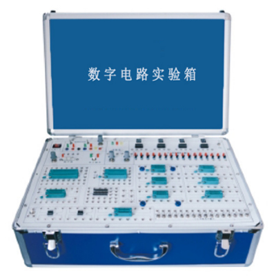

GLSD-1 digital circuit experiment box is mainly used for digital circuit experiments in electronics. It adopts a modular structure, and each module is independent of each other. Through the combination of different components in each component area, a variety of experimental circuits can be formed. The front of the experimental template is printed with a circuit diagram, and the back is equipped with devices. Each point to be tested in the experimental circuit is equipped with a test hole. It is easy to use, reliable in contact, long in life, and high in efficiency. The main experimental unit is completed with matching experimental modules. Experimental expansion modules can be selected according to different needs to complete related experimental content, which can meet the needs of digital circuit course experimental teaching.
GLSD-1 Digital Circuit Experiment Box
I、Equipment Overview
GLSD-1 Digital Circuit Experiment Box is mainly used for digital circuit experiments in electronics. It adopts a modular structure, and each module is independent of each other. Through the combination of different components in each component area, a variety of experimental circuits can be formed. The front of the experimental template is printed with a circuit diagram, and the back is equipped with devices. Each point to be tested in the experimental circuit is equipped with a test hole. It is easy to use, reliable in contact, and has a long life and high efficiency. The main experimental unit is completed with a matching experimental module. The experimental expansion module can be selected according to different needs to complete the relevant experimental content, which can meet the needs of digital circuit course experimental teaching.
This product is suitable for undergraduates, junior college students, and students in vocational colleges who offer experimental teaching of related courses such as "Digital Electronic Technology" and "Pulse Circuit". It is also suitable for product development and scientific research.
Ⅱ、Equipment configuration
1. Power supply: standard three-port power socket: directly connected to external AC 220V, the 220V AC is converted into ±l5V/0.5A, ±5V/0.5A through the power conversion unit inside the experimental box, all with short-circuit overload protection, automatic recovery function, connected to the main panel of the experimental box.
2. Equipment panel: the motherboard is made of 2mm thick printed circuit board, with component graphic symbols and corresponding connections printed on the front, printed circuits on the back, and related components soldered.
3. Signal source: provide a set of clock signal sources; adjustable clock signal source (low frequency, high frequency); single pulse source: positive and negative pulse output.
4. Logic input and display circuit:
provide a four-digit decimal decoding display, a set of dials, a sixteen-digit logic level switch, and a sixteen-digit logic level indicator.
5. Chip socket and multi-purpose device connector:
The chip socket is used to connect commonly used direct-plug package chips, and each pin is led to a universal plug hole for easy connection with other devices. Multi-purpose device connector, which can flexibly connect capacitors, resistors, transistors and other devices.
66 groups of 14Pin chip sockets, 5 groups of 16Pin chip sockets, 3 groups of 20Pin chip sockets (wide and narrow can be plugged),
2 groups of 40Pin chip sockets.
6. Other devices: 10K, 100K, 1M knob adjustable potentiometers, alarm indicator LED and buzzer, passive crystal oscillator 32768Hz, 4MHz, 6MHz, 12MHz each.
7. Others: 1 set of experimental wires, meeting the experimental needs and with margin, 1 experimental guide book.
III、Experimental projects of Digital Circuit Experiment Box
1. Transistor switching characteristics, limiters and clamps
2. TTL integrated logic gate logic function and parameter test
3. CMOS integrated logic gate logic function and parameter test
4. Integrated logic circuit connection and drive
5. Combinational logic circuit design and test
6. Decoder and its application
7. Data selector and its application
8. Trigger and its application
9. Counter and its application
10. Shift register and its application
11. Pulse distributor and its application
12. Use gate circuit to generate pulse signal - self-excited multivibrator
13. Monostable trigger and Schmitt trigger - pulse delay and waveform shaping circuit
14. 555 time base circuit and its application
15. D/A, A/D converters
16. Quiz answering device - comprehensive experiment
17. Electronic stopwatch - comprehensive experiment
18. Three-and-a-half-digit DC digital voltmeter - comprehensive experiment
19. Digital frequency meter - comprehensive experiment
20. Tug-of-war game machine - comprehensive experiment
21. Random access memory 2114A and its application - comprehensive experiment

Synchronous PC version:
GLSD-1 Digital Circuit Experiment Box https://www.biisun.com/home/category/detail/id/162.html