
 Italian
 German
 Russian
 Turkish
 Portuguese
 Spanish
 French
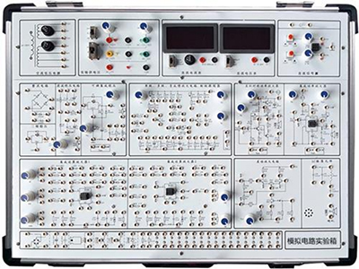

GLMD-1 Analog circuit experiment box adopts a mainboard plus module structure, which can meet the requirements of the experimental teaching syllabus and experimental teaching of "Analog Electronic Technology" in colleges and universities.
GLMD-1 Analog circuit experiment box
Ⅰ、Technical indicators
1. This analog circuit experiment box adopts a mainboard plus module structure, which can complete the experimental teaching outline and experimental teaching requirements of "Analog Electronic Technology" in colleges and universities;
2. DDS function signal source: sine wave (0-100KHZ), square wave and triangle wave (0-50KHZ), music signal; voltage Vpp: 0-10V;
3. Analog module film panel, marked circuit schematic;
4. Regulated fixed power supply: +12V (1A), -12V (1A), +5V (2A);
5. 2 adjustable power supplies: -5V to +5V adjustable Adjustment;
6. Standard independent development area, can design and develop various circuits;
7. Standard modules
① Transistor amplifier circuit module: complete single-stage amplifier circuit, two-stage amplifier circuit, negative feedback amplifier circuit, emitter follower experiment; bias, feedback, load adjustable;
② Differential amplifier module: complete double-ended differential mode amplification, single-ended differential mode amplification, double-ended common mode suppression experiment; adjustable zero;
③ Operational amplifier module: complete proportional summation, calculus circuit, voltage comparison, active low-pass high-pass band-stop filter experiment; integrated power amplifier experiment;
④ Waveform conversion module: square wave, duty cycle Adjustable rectangular wave, triangle wave, sawtooth wave generation experiment; integrated circuit RC sine wave oscillator, RC sine wave oscillator, LC oscillator and frequency selection amplifier experiment; square wave triangle wave conversion circuit, voltage current conversion circuit, voltage frequency conversion circuit experiment;
⑤ Power amplifier and voltage regulator module: rectifier filter, integrated voltage regulator, series parallel voltage regulator, complementary symmetrical power amplifier;
⑥ Signal source, voltage conversion and attenuation module: generate various signals required for the experiment, generate variable DC voltage and attenuate AC signal;
Ⅱ、Experimental content of analog circuit experiment box
1. Single-stage amplifier circuit
2. Two-stage amplifier circuit
3. Negative feedback amplifier circuit
4. Emitter follower
5. Differential amplifier circuit
6. Proportional summation circuit
7. Integral and differential circuit
8. Waveform generation circuit
9. Active filter
10. Voltage comparator
11. Integrated circuit RC sine wave oscillator
12. Integrated power amplifier
13. Current/voltage conversion circuit
14. Voltage/frequency conversion circuit
15. Waveform conversion circuit
16. Complementary symmetric power amplifier
17. Rectification filter and parallel voltage regulator circuit
18. Series voltage regulator circuit
19. Integrated voltage regulator circuit

Synchronous PC version:
GLMD-1 Analog circuit experiment box https://www.biisun.com/home/category/detail/id/163.html