
 Italian
 German
 Russian
 Turkish
 Portuguese
 Spanish
 French

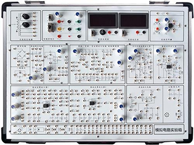
GLSM-01 Digital circuit and analog circuit comprehensive experiment box is mainly used for digital circuit and analog circuit experiments in electronics. It adopts a modular structure, and each module is independent of each other. Through the combination of different components in each component area, a variety of experimental circuits can be formed. The front of the experimental template is printed with a circuit diagram, and the back is equipped with devices. Each point to be tested in the experimental circuit is equipped with a test hole. It is easy to use, reliable in contact, long in life and high in efficiency. The main experimental unit is completed with matching experimental modules. Experimental expansion modules can be selected according to different needs to complete related experimental content, which can meet the needs of course experimental teaching.
GLSM-01 Digital circuit and analog circuit comprehensive experiment box
Ⅰ、Equipment Overview
GLSM-01 Digital circuit and analog circuit comprehensive experiment box is mainly used for digital circuit and analog circuit experiments in electronics. It adopts a modular structure, and each module is independent of each other. Through the combination of different components in each component area, a variety of experimental circuits can be formed. The front of the experimental template is printed with a circuit diagram, and the back is equipped with devices. Each point to be tested in the experimental circuit is equipped with a test hole. It is easy to use, reliable in contact, long in life and high in efficiency. The main experimental unit is completed with matching experimental modules. Experimental expansion modules can be selected according to different needs to complete related experimental content, which can meet the needs of course experimental teaching.
Ⅱ、Equipment configuration
1. Power supply: Input: AC 220V±10%, 50HZ, Output: DC: +5V, I≥1A, DC: ±12V, I≥0.2A, DC: -5V~-12V adjustable, I≥0.2A, DC: +5V~+27V adjustable, I≥0.2A, each output has overcurrent protection and automatic recovery function, AC V: 7.5V×2; AC I≥0.15A.
2. DC signal source: dual-channel –0.5V~+0.5V; –5V~+5V two-speed continuously adjustable.
3. Function generator: output frequency: 2Hz~90KHz, four-speed output square wave (0~20V), triangle wave (0~15V), sine wave (0~10V).
4. 2 sets of manual single pulse circuits (with debounce): Each set can output positive and negative pulses at the same time, and the pulse amplitude is TTL level.
5. 10 fixed frequency pulse sources, output is TTL level: 1Hz, 10Hz, 100Hz, 1KHz, 10KHz, 100KHz, 500KHz, 1MHz, 5MHz, 10MHz;
6. Digital LED display: (1) LED0~LED3 consists of 4-digit seven-segment common cathode LED digital tubes and binary-decimal decoders (2) LED4~LED5 two-digit seven-segment segment codes a.b.c.d.e.f.g.h are connected to the jack through resistors.
7. 12-bit logic level input switch: can input low level ‘0’ and high level ‘1’ (positive logic).
8. 12-bit logic level indicator light: the indicator light is on for high level ‘1’, and the indicator light is off for low level ‘0’.
9. 1 set of BCD code dials, which can generate four sets of BCD code digital signals.
10. Four-digit digital frequency meter: measurement range 0~1MHz, used to measure square wave, triangle wave and sine wave.
11. Speaker and drive circuit. It is a sound-generating device for clock time, alarm and music.
12. Potentiometer group: 1K, 10K, 100K, 1M each.
13. Open experimental area (component library): provides 9 locking sockets (3 14-pin, 5 16-pin), another 40-pin locking socket, and 1 8-pin round hole IC socket. Provide components such as resistors, capacitors, diodes, triodes, and three-terminal voltage regulators.
14. Experimental module circuit: (1) Rectification and filtering circuit (2) Series voltage regulator circuit (3) Adjustable voltage regulator circuit (4) Power amplifier (5) Integrated operational amplifier circuit.
15. All signal input and output jacks are gold-plated, non-oxidizing, non-discoloring, and good contact.
16. Aluminum alloy experimental box, fireproof board, sturdy and durable, beautiful and generous style.
17. Dimensions: 530mm×360mm×100mm.
18. Digital acquisition system:
III、Experimental projects of this Digital circuit and analog circuit comprehensive experiment box
(I) Analog experiment
1. Common electronic instrument use practice, use multimeter to test diode and transistor parameters
2. Single-stage amplifier circuit
3. Two-stage amplifier circuit
4. Negative feedback amplifier circuit
5. Emitter follower
6. Differential amplifier circuit
7. Integrated operational amplifier parameter test
8. Proportional summation operation circuit
9. Integral and differential circuit
10. Waveform generation circuit
11. Active filter
12. Voltage comparator
13. Integrated circuit RC sine Wave oscillator
14. Integrated power amplifier
15. Rectification filter and parallel voltage regulator circuit
16. Series voltage regulator circuit
17. Integrated voltage regulator
18. RC sine wave oscillator
19. LC oscillator and frequency selection amplifier
20. Current/voltage conversion circuit
21. Voltage/frequency conversion circuit
22. Complementary symmetric power amplifier
23. Waveform conversion circuit
24. Field effect tube experiment
25. SCR experimental circuit comprehensive experiment
26. Design and debugging of multimeter composed of operational amplifier.
(II) Digital electronics experiment
1. Gate circuit logic function and test experiment
2. Combinational logic circuit (half adder, full adder and logic operation) experiment
3. Trigger experiment (I) R-S, D, JK
4. Trigger experiment (II) Three-state output trigger, latch
5. Timing circuit test and research
6. Integrated counter and register experiment
7. Decoder and data selector experiment
8. Waveform generator and monostable trigger experiment
9. 555 time base circuit experiment
Optional experiments include the following
10. Transistor switching characteristics, limiter and clamp experiment
11. TTL gate circuit parameter test experiment
12. CMOS gate circuit test experiment
13. Analog-to-digital A/D conversion circuit experiment
14. Digital-to-analog D/A conversion circuit experiment
15. Timing circuit application experiment
16. Four-way priority decision circuit experiment
17. Quiz answer machine experiment

Synchronous PC version:
GLSM-01 Digital circuit and analog circuit comprehensive experiment box https://www.biisun.com/home/category/detail/id/164.html