
 Italian
 German
 Russian
 Turkish
 Portuguese
 Spanish
 French

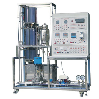
PCS-D process control system experimental equipment can realize the experiment and training functions of pressure, flow, liquid level fixed value adjustment system, as well as ratio, cascade, feedforward-feedback and other complex adjustment systems. The controlled object is provided with an interface control box, the power supply and signal of the control box are separated, and the control box includes a power supply device, a frequency converter, an intelligent regulator and basic protection devices of the equipment, and provides an expansion interface.
PCS-D process control system experimental equipment
Ⅰ、Product Overview
This system can realize the experimental and training functions of pressure, flow, liquid level constant value regulation systems, as well as ratio, cascade, feedforward-feedback and other complex regulation systems. The controlled object is provided with an interface control box, the power supply and signal of the control box are separated, and the control box includes a power supply device, a frequency converter, an intelligent regulator and basic protection devices for the equipment, and provides an expansion interface.
Ⅱ、Main features and requirements of the system
1. The regulated parameters include thermal parameters such as flow, pressure, and liquid level. The actuators include actuators for regulating valve instruments and electric drive drivers for variable frequency speed regulators. In addition to changing the set value of the regulator for step disturbance, the system can also create disturbances in the object through solenoid valves and hand-operated valves;
2. A regulated parameter can evolve into multiple regulation loops under different power sources, different actuators, and different process lines. By making different combinations of the object system and combining different experimental purposes, dozens of process control experiments can be carried out.
III、Performance index requirements
1. Input power: three-phase four-wire 380V and single-phase three-wire 220V±10%;
2. Working environment: temperature -10℃~+40℃, relative humidity ≤85%;
3. Device capacity: 2kVA;
4. External dimensions are approximately 1200mm*780mm*1830mm;
IV、Device composition requirements
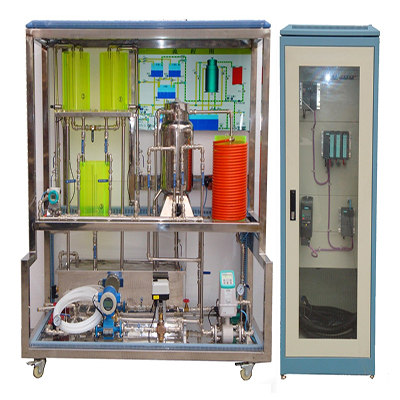
The system object is mainly composed of a stainless steel frame, a stainless steel water storage tank, three series-connected organic glass water tanks and plastic-coated stainless steel pipes. The water supply system has two routes: one route is composed of a single-phase magnetic drive pump, an electric regulating valve, an electromagnetic flowmeter and a manual switch valve; the other route is composed of a frequency converter, a variable frequency magnetic drive pump, a turbine flowmeter and a manual switch valve. The specific configuration is as follows:
1. Control object:
(1) Steel frame: stainless steel;
(2) Water storage tank: volume 150L, to meet the experimental water supply needs of the upper, middle and lower water tanks. The bottom of the water tank is equipped with a water outlet valve;
(3) Liquid level water tank: including upper, middle and lower liquid level water tanks. The bottom of the water tank is connected to a diffused silicon pressure sensor and a transmitter. The upper, middle and lower water tanks can be combined into a first-order, second-order and third-order single-loop liquid level control system and a double closed-loop and three-closed-loop liquid level cascade control system;
(4) Water pump: A magnetic drive pump is used as the water supply system, with a flow rate of 30 liters/minute, a head of 8 meters and a power of 180W. The pump body is made entirely of stainless steel. This device uses two magnetic drive pumps, one for a single-phase 220V constant pressure drive and the other for a three-phase variable frequency 220V output drive;
(5) Pipes and valves: The entire system pipeline is connected by plastic-coated stainless steel pipes, and the manual valves are all ball valves. The waterway can be freely selected to switch the connection status of the pipeline;
(6) Solenoid valve: The solenoid valve is a normally closed solenoid valve with an operating temperature of -5 to 80°C.
2. Field instruments:
(1) Pressure transmitter: Adopt industrial diffused silicon pressure transmitter with stainless steel isolation diaphragm, use signal isolation technology, and follow and compensate for sensor temperature drift. The range is 0-200KP, the accuracy is 0.5 level, 24VDC power supply, and output 4-20mA standard signal;
(2) Liquid level transmitter: Adopt industrial diffused silicon pressure transmitter with stainless steel isolation diaphragm, use signal isolation technology, and follow and compensate for sensor temperature drift. The range is 0-5KP, the accuracy is 0.5 level, and output 4-20mA standard signal;
(3) Electromagnetic flow sensor: Adopt sensor-transmitter integrated electromagnetic flowmeter, flow range: 0-1.5/h, measurement accuracy ±0.5%, output 4-20mA standard signal; (electromagnetic flow sensor and converter)
(4) Turbine flowmeter: The sensor part of the turbine flowmeter is a turbine structure. The transmitter is powered by 24V DC, has a 4-20mA transmission output, and an accuracy of 1.0. It is a flow detection device with a high-precision sensor and transmitter integrated structure, which is used to detect the branch flow of the variable frequency pump and the outlet flow of the coil;
(5) Electric control valve: An intelligent straight-stroke electric control valve is used to adjust the flow of the control loop. The control unit is integrated with the electric actuator, the power supply is single-phase 220V, the control signal is 4-20mADC or 1-5VDC, and the output is a valve position signal of 4-20mADC;
(6) Frequency converter: The control signal input is 4-20mADC, and the AC 220V frequency conversion output is used to drive a three-phase magnetic drive pump.
3. Control box:
(1) Experimental object interface box: The control object interface box is divided into a power box and a signal interface box. The power box contains power supply devices and power distribution switches and other strong electrical devices; the signal interface box is mainly an intermediate interface for connecting weak current signals with the extended control system;
(2) Intelligent instrument components: digital intelligent digital display/with communication interface, alarm, etc., capable of realizing double closed-loop liquid level control.
(3) Switching power supply: input voltage 220VAC; output voltage 24VDC; rated power 100W;
(4) AC contactor: 220V
(5) Intermediate relay: DC24V
(6) Wiring terminal: good insulation, sturdy and durable
(7) Isolator: used for signal isolation and conversion, can convert 0-10V voltage signal into 4~20mADC output.
V、Experimental items
1. Basic system test experiment
(1) Pressure, liquid level and flow measurement experiment
(2) Pump load characteristic measurement experiment
(3) Variable frequency pump control characteristic measurement experiment
2. Object characteristic measurement research experiment
(1) Single-capacity water tank liquid level mathematical model measurement experiment
(2) Double-capacity water tank liquid level mathematical model measurement experiment
(3) Electric control valve flow characteristic measurement experiment
3. Single-loop control system experiment
(1) Single-capacity water tank liquid level constant value control experiment
(2) Double-capacity liquid level constant value control experiment
(3) Single closed-loop flow control experiment
(4) Single closed-loop pressure control experiment
4. Cascade control system experiment
(1) Double closed-loop water tank liquid level cascade control experiment
(2) Water tank liquid level and inlet flow cascade control experiment
5. Flow ratio control experiment
(1) Single closed-loop flow ratio control system
(2) Variable ratio control experiment
6. Feedforward-feedback control experiment
VI、Technical performance
1. Input power: single-phase three-wire 220V±10%
2. Working environment: temperature 10℃~40℃, relative humidity ≤85%
3. Device capacity: 1.0kVA
4. Dimensions: 800mm*600mm*1850mm (length*width*height)
5. Protection function: The device has grounding protection and leakage protection functions, and its safety meets relevant national standards.
VII. DCS control system
1. Clearly layered three-layer network structure: covering the Ethernet bus of the operation layer, the industrial Ethernet bus of the control layer, and the field layer bus.
2. Hardware processing capacity:
The control station main control unit CPU Pentium II, with 34M memory, of which 2M is SRAM; I/O signal processing units are all intelligent structures.
3. System processing capacity:
One system supports 8 domains, and each domain has a processing capacity of 10,000 physical I/O points and 1,000 control loops.
4. Main controller module:
Input voltage: 21.6~26.4VDC. Module redundancy: support, master-slave hot standby redundancy, redundancy switching time 50ms, power-off retention SRAM: 1M Bytes. Power-off protection: working mode: backup battery retention; data retention time after power off: 2 years
System network: Ethernet: 100Mbps. Working mode: dual network redundancy, communication rate: 187.5Kbps, 500Kbps, l.5Mbps.
5. Main controller backplane module: supports 4 modules, the two slots on the left are for main controller modules, and the two slots on the right are for IO-BUS modules. The external interfaces of the main control module and IO-BUS module are located on the 4-slot main control base.
6. System power supply module: realize the conversion of AC 110VAC/220VAC to DC 24VDC, input and output isolation, output rated power 120W.
7. Auxiliary power supply module: realize the conversion of 220VAC to 24VDC output, input and output isolation; with output short circuit protection function, power supply automatically recovers after fault elimination.

Synchronous PC version:
PCS-D process control system experimental equipment https://www.biisun.com/home/category/detail/id/166.html