
 Italian
 German
 Russian
 Turkish
 Portuguese
 Spanish
 French
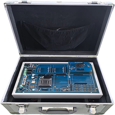

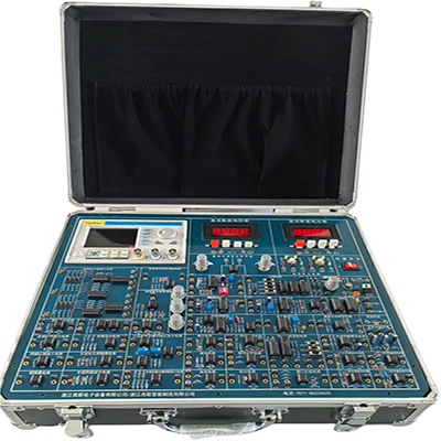
GLDPJ-2A Measurement and control training equipment is a key equipment used in engineering teaching, scientific research verification and industrial testing, covering multiple fields such as instrumentation and science and technology, sensor technology, electronic information technology, process control systems, hydraulic transmission technology, and material mechanics.
GLDPJ-2A Measurement and control training equipment
Ⅰ、Equipment features
1. Adopts the high-performance MCU-STM32F103ZET6 imported from STMicroelectronics (ST) based on the ARM CORTEX-M3 core
2. The core board and the main board can be used separately, integrating simulation debugging, programming, and downloading functions, suitable for teaching, innovation, competition, etc.
3. The CPU resource IO port is open to users.
4. Contains protection circuit, and the simulator and user circuit adopt isolation technology (optional matching isolation debugger).
5. The mainboard hardware resource automatic detection function is more convenient for maintenance and application.
6. This measurement and control training equipment module includes: analog quantity conditioning circuit (PT100 conditioning and collecting temperature, external ADC), switch quantity conditioning circuit (optocoupler isolation, comparator integer, 74 series chip buffer output), relay, LED six-segment digital tube area AD/DA experimental area, infrared transmission and reception, I/O port expansion (input and output IIC expansion or serial to parallel parallel to serial similar to heating expansion module), keyboard display (display by LED light indicating status), voice amplifier (with amplifier module), temperature sensor, ultrasonic ranging, DC/stepping motor (DC motor drive and speed measurement integrated module for speed PID control), key switch (mainboard supporting independent key), 485 expansion module (mainboard supporting), Bluetooth (AT command control), ZigBee wireless communication (AT command control), GPRS phone text message (AT command control), wireless remote control (supporting wireless module 2.4G communication), human infrared sensing alarm module, universal experimental expansion area can carry out secondary development and innovation experimental module and many other experiments.
Ⅱ、Functional parameters
1. Processor: STM32F103ZET6.
2. Program download method: JLINK or STLINK, 20Pin SWD interface.
3. Functional motherboard
① Power supply: Use DC12V/2A power adapter for power supply.
② MCU: STM32F103ZET6, all IOs are led out with double-row pins.
③ Communication interface: Equipped with 1 RS485 interface (compatible with Siemens PPI cable interface, DB9 female), 1 RS232 interface (DB9 female), 1 CAN interface.
④ Buttons: 8 independent buttons, 1 4×4 matrix keyboard interface (matching matrix keyboard module).
⑤ Display: 8 LED indicators, 1 RGB three-color LED light, 1 LCD12864 interface, 1 LCD1602 interface, 1 TFT480×320 display interface (with resistive touch).
⑥ Switch input interface: 4-channel digital input, optocoupler isolation input, comparator shaping, 74HC14 processing and then read to MCU.
⑦Switch output interface: 2 relays with indicator lights.
⑧Others: 1 passive buzzer, 1 active buzzer, 1 DAC output driver LED, 1 2K potentiometer (0 ~ 3.3V voltage signal output), single pulse generation circuit. .
⑨Equipped with SD card holder, default SDIO interface, can realize the reading and writing of SD files and the operation of FAT file system.
⑩Expansion interface: 1 Arduino standard expansion interface.
4. Temperature control module: with NTC temperature sensor, 18B20 single bus temperature sensor, and 2-way PWM thermal resistor. The temperature sensor is sandwiched between the heating resistor, and this module can be used as a temperature control system.
5. RTD temperature detection module: equipped with PT100 sensor, op amp conditioning input, and external ADC to realize sensor temperature monitoring.
6. Stepper motor module: The stepper motor is controlled by PWM1, PWM2, PWM3, and PWM4 four-way output, which can realize the control of 42-type two-phase stepper motor.
7. DC motor module: It uses an integrated DC motor driver IC and is equipped with a Hall speed sensor, which can be used for speed closed-loop control.
8. FM radio module: The FM radio module uses the IIC (SCL, SDA) bus method to realize automatic channel search or set a fixed frequency value function.
9. Audio amplifier module: The output channel is connected to the amplifier input to realize the sound playback function of different sound sources.
10. MP3 module: It uses the JQ8900 audio decoding chip to decode MP3 format files. The output R and L channels can be used as the input of the amplifier to realize the SD card music playback function.
11. LED display module: 74HC595 expands 6-bit digital tube dynamic display, equipped with 4 LEDs and 4 buttons.
12. LED 16×16 dot matrix display module: It uses 4 74HC595 drivers and dynamic scanning display.
13. DC motor module: DC motor control is by PWM1, PWM2, which can realize speed regulation or forward and reverse control;
14. Infrared communication module: MCU controls infrared light-emitting tube to emit infrared signal, and receives decoding receiving head signal to realize self-transmitting communication.
15. Ultrasonic ranging module: MCU controls ultrasonic generating circuit to generate ultrasonic signal, and demodulation circuit outputs signal to MCU to realize ranging. Each signal node has test points.
16. Bluetooth module: uses integrated module serial port AT command communication.
17. ZigBee module: uses serial port transparent transmission function to realize functions such as wireless data transmission and reception or wireless remote control.
18. GPRS phone SMS module: can control the sending and receiving of SMS through serial port AT command.
19. 2.4G wireless communication module: Nrf24L01 wireless module, SPI interface.
20. Human infrared sensor module: detects human infrared signal and can output switch signal.
21. Switch quantity conditioning circuit
(1) Input conditioning: high power input conditioning (optical coupler isolation)
Low power input conditioning (capacitor de-jitter)
(2) Output conditioning: DC load drive circuit (power transistor, Darlington transistor, etc.)
Thyristor load drive circuit
Relay drive circuit
For example: DC motor speed control experiment, stepper motor forward and reverse control experiment
It is required that each signal node has a test point.
22. Analog quantity conditioning circuit
(1) Input conditioning: small signal amplification, filtering, frequency signal amplification and shaping, AD conversion
(2) Output conditioning: filtering, current-voltage conversion, amplification
It is required that each signal node has a test point, focusing on the signal conditioning process, and no specific object is required. .
23. Infrared communication
(1) MCU control realizes self-transmitting and receiving communication
(2) Infrared remote control decoding experiment
It is required that each signal node has a test point.
24. PID control system experiment
(1) Single closed-loop control experiment, requiring the use of position algorithm and incremental control algorithm respectively. Through the experiment, students can understand the different control effects of the two algorithms.
(2) Double closed-loop control experiment.
25. The wiring holes for the main functional wiring in the experiment are reserved for students to connect by themselves. .
26. The software is accompanied by circuit diagrams, schematic diagrams, flow charts, experimental connection diagrams, chip query diagrams, and experimental instructions for each experiment, and provides detailed teaching experimental courseware.
III、Experimental projects of this measurement and control training equipment
1. LED flashing experiment
2. LED Flowing light experiment
3. Matrix keyboard experiment
4. Buzzer experiment
5. Serial communication experiment
6. Relay control experiment
7. RGB light control experiment
8. Digital tube display experiment
9. TFT LCD display experiment
10. LCD1602 LCD display experiment
11. LED16×16 dot matrix display experiment
12. ADC conversion experiment
13. DAC experiment
14. Smart radio design
15. PWM DC motor speed control system design
16. Analog signal acquisition experiment (using NTC temperature, etc., to collect and upload to RS485 interface or RS232 interface) )
17. MP3 music player design
18. Digital signal switch quantity acquisition experiment (using independent buttons, acquisition and upload to RS485 interface or RS232 interface)
19. Temperature control closed-loop system design
20. DC motor speed measurement and control experiment;
21. Stepper motor speed regulation system design
22. Infrared communication experiment (infrared remote control decoding experiment)
23. Human infrared induction alarm and infrared ranging experiment
24. Ultrasonic sensor application design
25. Temperature, humidity, thermistor application design
26. Multi-location lighting control system design
27. NRF24L01 2.4G wireless remote control experiment

Synchronous PC version:
GLDPJ-2A Measurement and control training equipment https://www.biisun.com/home/category/detail/id/177.html