
 Italian
 German
 Russian
 Turkish
 Portuguese
 Spanish
 French
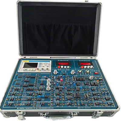

GLCK-2 measurement and control circuit experimental platform consists of signal generating circuit, signal amplifying circuit, signal processing circuit, signal detection and conversion circuit, etc. It is suitable for the teaching of precision instruments, measurement and control technology, instruments and other related majors.
GLCK-2 measurement and control circuit experimental platform
Ⅰ、Overview
This measurement and control circuit experimental platform consists of signal generation circuit, signal amplification circuit, signal processing circuit, signal detection conversion circuit, etc. It is suitable for teaching related majors such as precision instruments, measurement and control technology, and instruments.
Ⅱ、Main functional modules
1. DC regulated power supply:
Six channels: ±5V/0.5A, ±12V/0.5A, two channels 0-18V/0.5A, all with short-circuit protection sound alarm function.
2. Function signal generator and digital frequency meter:
The series is a signal generator based on direct digital synthesis technology (DDS), using FPGA design and DC9V-DC36V wide voltage power supply. It can output sine, square wave (duty cycle can be adjusted from 1% to 99%), triangle wave and sawtooth wave and other function waveforms. The maximum effective output exceeds 10Vpp, the frequency ranges from 0.01Hz-2MHz, and the resolution is 10mHz. It also has TTL synchronous output and multiple functions such as counter and 60MHz frequency meter. It is easy to use, has high signal stability, and the output signal can adjust the amplitude and DC bias. It also has a frequency sweep function, supports linear sweep and logarithmic sweep, and can arbitrarily set the sweep frequency range and sweep time. It is an ideal equipment for electronic enthusiasts, laboratories, production lines, teaching, and scientific research. It can also be used as a supporting module for industrial equipment.
(1) High frequency accuracy: The frequency accuracy can reach 10-6.
(2) High frequency resolution: The full range frequency resolution is 10mHz.
(3) No range limit: The full range frequency is not divided into steps and can be directly set digitally.
(4) High waveform accuracy: The output waveform is synthesized by the function calculation value, with high waveform accuracy and low distortion.
(5) Multiple waveforms: sine, square wave, triangle wave, sawtooth wave.
(6) Sweep characteristics: It has a frequency sweep function, and the start and end points of the sweep can be set arbitrarily.
(7) Storage characteristics: It can store 10 groups of user-set instrument status parameters, which can be called up and reproduced at any time.
(8) Operation mode: All key operations, LCD1602 liquid crystal English display, direct digital setting or knob continuous adjustment.
(9) High reliability: Large-scale integrated circuit, surface mount technology, high reliability and long service life.
(10) Frequency measurement: With built-in 60MHz frequency meter function, frequency measurement of internal/external signals.
(11) Output channel: One main waveform output and one main waveform synchronized TTL level output.
(12) Output waveform: sine wave, square wave (adjustable duty cycle), triangle wave, rising sawtooth wave, falling sawtooth wave.
(13) Output amplitude: ≥10Vp-p (no load)
(14) Output impedance: 0Ω±10%
(15) Counting range: 0-4294967295
(16) Frequency measurement range: 1Hz~60MHz
3. DC digital voltmeter:
Range 0~20V, divided into three gears: 200mV, 2V, and 20V.
4. Rich experimental modules:
Provide general circuits, differential amplifier circuits, window comparison circuits, resistor subdivision circuit units and other modules.
Ⅲ、Experimental content of this measurement and control circuit experimental platform
1. Differential amplifier experiment
2. Signal amplifier experiment
3. Signal operation circuit experiment
4. Voltage comparator experiment
5. Resistor chain phase subdivision experiment
6. Amplitude modulation and demodulation experiment
7. Phase modulation bridge experiment
8. Pulse width modulation circuit experiment
9. Frequency modulation and discrimination experiment
10. Switching multiplication modulation and demodulation experiment
11. Precision rectification full detection experiment
12. Switching full-wave phase-sensitive detection experiment
13. Voltage follower circuit experiment
14. AC voltage follower experiment
15. Bootstrap combination amplifier circuit experiment
16. Dual op amp inverting series type high common mode suppression amplifier circuit Experiment
17. Experiment of dual op amp in-phase series high common mode rejection amplifier circuit
18. Experiment of three op amp high common mode rejection ratio amplifier circuit
19. Experiment of switch-type multiplication amplitude modulation circuit
20. Experiment of resistance change pulse width modulation circuit
21. Experiment of voltage change pulse width modulation circuit
22. Experiment of second-order active low-pass filter circuit
23. Experiment of second-order active high-pass filter circuit
24. Experiment of second-order active band-pass filter circuit
25. Experiment of second-order active band-stop filter circuit
26. Experiment of switch capacitor filter circuit
27. Experiment of resistor chain subdivision circuit
28. Experiment of phase-locked loop circuit
29. Experiment of phase-locked loop frequency multiplication circuit
30. Experiment of frequency division circuit

Synchronous PC version:
GLCK-2 measurement and control circuit experimental platform https://www.biisun.com/home/category/detail/id/178.html